ICOc Documentation
1 ICOc
ICOc is a
- Python library and
- collection of tools and scripts
for the ICOtronic system. Currently the main purpose of the software is:
- Data Collection via
- the script
icoc(Windows only) or - the script
icon(Linux, macOS, Windows) or - directly via the API (Linux, macOS, Windows)
- the script
- Testing the functionality of
- Stationary Transceiver Unit (STU) and
- sensor devices/nodes, such as
The software reads data from the Stationary Transceiver Unit (STU) via CAN using the MyTooliT protocol. The STU itself reads from and writes data to the sensor devices via Bluetooth.
Notes:
The command line tool
icocrequires Microsoft Windows 10 (tested) or Windows 11 (untested).The
- test suite (except for the deprecated verification tests),
icon, and- the (new) API
use python-can and therefore also works on Linux and macOS. The ICOc measurement tool does not. For more information on how to use (parts of) the ICOc software on Linux, please take a look here.
For more information about other required software components, please read the subsection “Software” in this document.
1.1 Requirements
1.1.1 Hardware
In order to use ICOc you need at least:
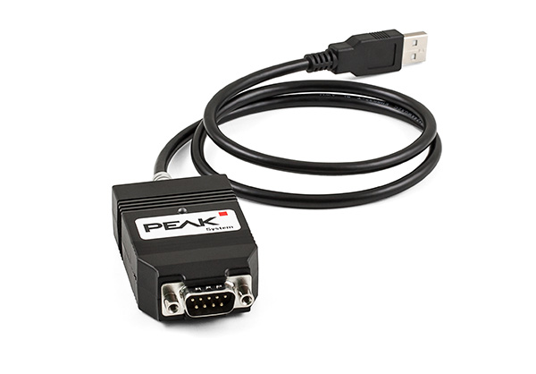
a PCAN adapter:
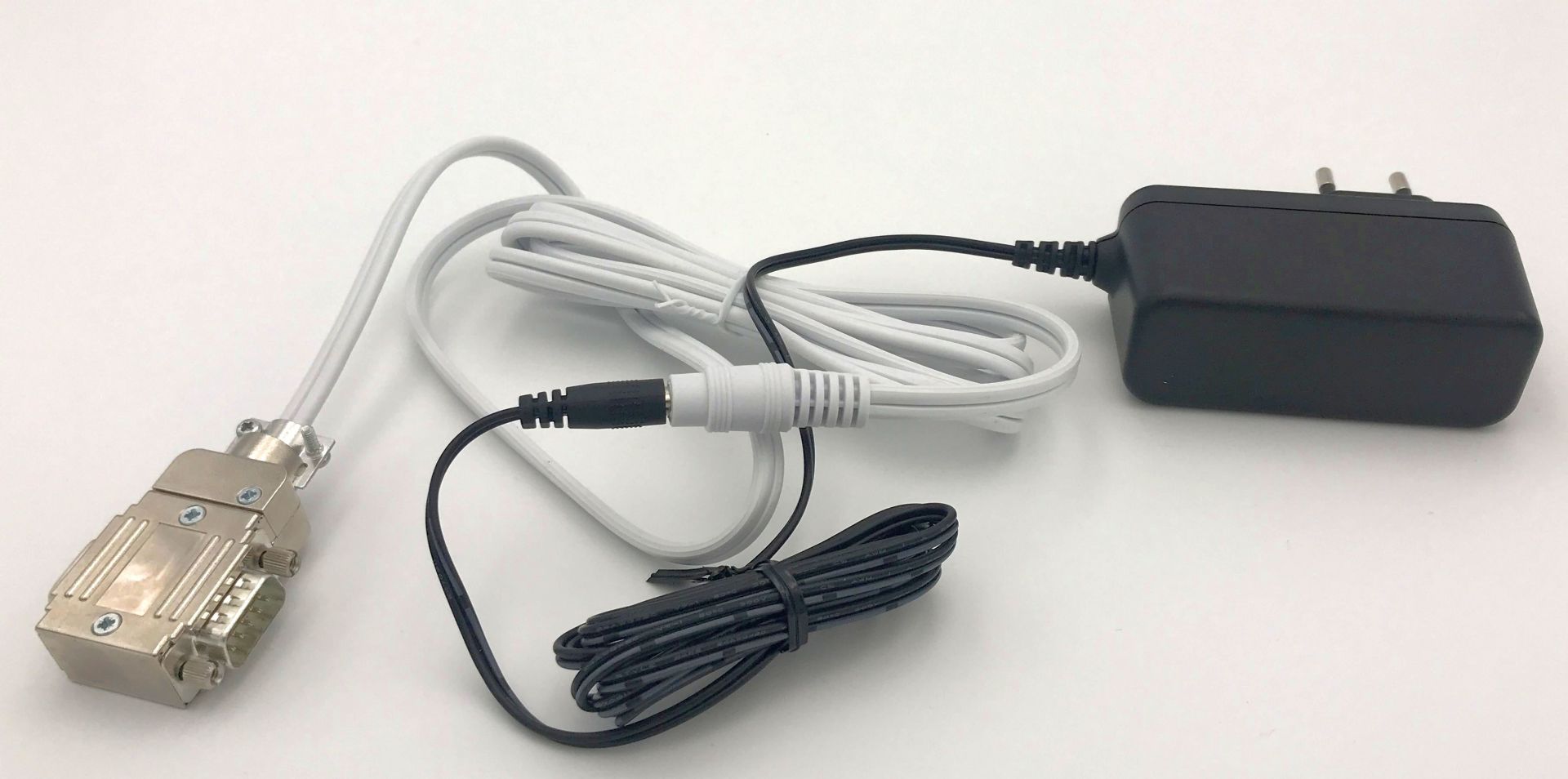
including:
power injector, and
power supply unit (for the power injector):
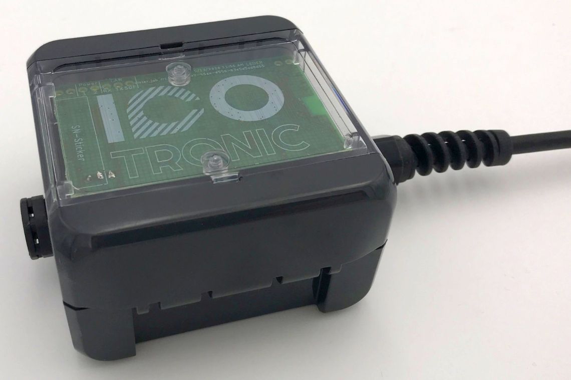
a Stationary Transceiver Unit:
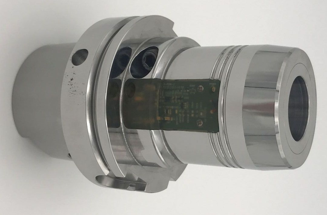
a sensor device, such as a Sensory Tool Holder:
1.1.1.1 Setup
- Connect the power injector
- to the PCAN adapter, and
- the power supply unit.
- Connect the USB connector of the PCAN adapter to your computer.
- Make sure that your sensor device (SHA/STH/SMH) is connected to a power source. For an STH this usually means that you should check that the battery is (fully) charged.
1.1.2 Software
1.1.2.1 Python
ICOc requires at least Python 3.10. The software also supports Python 3.11 and 3.12. We recommend you use the 64-bit version of Python.
You can download Python here. When you install the software, please do not forget to enable the checkbox “Add Python to PATH” in the setup window of the installer.
1.1.2.2 PCAN Driver
To communicate with the STU you need a driver that works with the PCAN adapter. The text below describes how to install/enable this driver on
1.1.2.2.1 Linux
You need to make sure that your CAN adapter is available via the SocketCAN interface.
The following steps describe one possible option to configure the CAN interface on (Fedora, Ubuntu) Linux manually.
Connect the CAN adapter to the computer that runs Linux (or alternatively the Linux VM)
Check the list of available interfaces:
The command output should list the CAN interface with the name
can0Configure the CAN interface with the following command:
sudo ip link set can0 type can bitrate 1000000Bring up the CAN interface
sudo ip link set can0 up
You can also configure the CAN interface automatically. For that purpose please store the following text:
in a file called /etc/systemd/network/can.network. Afterwards enable networkd and reload the configuration with the commands:
sudo systemctl enable systemd-networkd
sudo systemctl restart systemd-networkd
# Note: The command `networkctl reload` only works in systemd 244 or newer
sudo networkctl reload || sudo systemctl reload systemd-networkd
You can check the status of the CAN connection with the command:
If everything works as expected, then the output of the command should look similar to the text below:
IDX LINK   TYPE     OPERATIONAL SETUP
  …
7 can0 can carrier configuredSources:
1.1.2.2.2 macOS
On macOS you can use the PCBUSB library to add support for the PCAN adapter. For more information on how to install this library please take a look here.
1.1.2.2.3 Windows
You can find the download link for the PCAN Windows driver here. Please make sure that you include the “PCAN-Basic API” when you install the software.
1.1.2.3 Simplicity Commander (Optional)
For the tests that require a firmware flash you need to either install
If you choose the first option, then please make sure to install the Simplicity Commander tool inside Simplicity Studio.
1.1.2.3.1 Linux
Please add the path to commander to the list commands → path → linux in the configuration.
1.1.2.3.2 macOS
If you install Simplicity Studio or Simplicity Commander in the standard install path (/Applications) you do not need to change the config. If you put the application in a different directory, then please add the path to commander to the list commands → path → mac in the configuration.
1.1.2.3.3 Windows
If you installed Simplicity Studio (including Simplicity Studio) to the standard location, then you do not need to change the configuration.
If you download Simplicity Commander directly, then the tests assume that you unzipped the files into the directory
C:\SiliconLabs\Simplicity Commander.If you did not use any of the standard install path, then please add the path to
commander.exeto the listcommands→path→windowsin the configuration.
1.1.2.3.4 Additional Notes
- If you do not want to change the config, and Simplicity Commander (
commander) is not part of the standard locations for your operating system, then please make sure thatcommanderis accessible via thePATHenvironment variable. - Please note, that you do not need to install Simplicity Commander if you just want to measure data with ICOc.
1.2 Install
Please use the following command:
to install the latest official version of ICOc from PyPi. Afterwards you can use the various scripts included in the package.
1.2.1 Install the Package Using Windows Terminal
Install (Windows) Terminal if you have not done so already; On Windows 11 this application should be installed by default.
Open Terminal
Copy and paste the following text into the Terminal
Press Return ⏎
Wait until the install process finished successfully
1.2.2 Install the Development Version of ICOc
Note: Please only use the command below, if you know what you are doing!
1.2.3 Troubleshooting
1.2.3.1 Import Errors
If one of the tests or ICOc fails with an error message that looks similar to the following text:
Traceback (most recent call last):
…
    from numexpr.interpreter import MAX_THREADS, use_vml, __BLOCK_SIZE1__
ImportError: DLL load failed while importing interpreter: The specified module could not be found.

DLL load failed while importing interpreter: The specified module could not be found.
then you probably need to install the “Microsoft Visual C++ Redistributable package”. You can download the latest version
1.2.3.2 Insufficient Rights
If you do not have sufficient rights to install the package you can also try to install the package in the user package folder:
1.2.3.3 Unable to Install in Editable Mode
If the ICOc install fails with the following error:
ERROR: Project …/ICOc has a 'pyproject.toml' and its build backend is missing the 'build_editable' hook.
Since it does not have a 'setup.py' nor a 'setup.cfg', it cannot be installed in editable mode.
Consider using a build backend that supports PEP 660.
then your version of Setuptools needs to be updated before you install ICOc. You can use the following command to do that:
1.2.3.4 Unable to Locate HDF5
The installation of ICOc might fail with an error message that looks like this:
… implicit declaration of function 'H5close'If you uses Homebrew on an Apple Silicon based Mac you can use the following commands to fix this problem:
pip uninstall -y tables
brew install hdf5 c-blosc2 lzo bzip2
export BLOSC_DIR=/opt/homebrew/opt/c-blosc
export BZIP2_DIR=/opt/homebrew/opt/bzip2
export LZO_DIR=/opt/homebrew/opt/lzo
export HDF5_DIR=/opt/homebrew/opt/hdf5
# Require version 3.9.1, since 3.9.2 might fail because of an
# “Illegal instruction” error:
# https://github.com/PyTables/PyTables/issues/1093
pip install --no-cache-dir tables==3.9.1
1.2.3.5 HDF5 Library Not Loaded
Some of the ICOc commands might fail with an error message that looks like this on macOS:
Library not loaded: /opt/homebrew/opt/hdf5/lib/libhdf5.….dylib
In that case you might have installed an outdated cached version of PyTables. You should be able to fix this issue using the same steps as described above.
1.2.3.6 Unable to open OpenBLAS library
If one of the ICOc command fails with the error message:
ImportError: libopenblas.so.0: cannot open shared object file: No such file or directory
on Raspbian (or some other GNU/Linux version based on Debian) then you probably need to install the OpenBLAS library:
1.2.3.7 Unknown Command icoc
If pip install prints warnings about the path that look like this:
The script … is installed in
'…\Scripts'which is not on PATH.
then please add the text between the single quotes (without the quotes) to your PATH environment variable. Here …\Scripts is just a placeholder. Please use the value that pip install prints on your machine. If
- you used the installer from the Python website (and checked “Add Python to PATH”) or
- you used winget
to install Python, then the warning above should not appear. On the other hand, the Python version from the Microsoft Store might not add the Scripts directory to your path.
1.3 Basic Usage
1.3.1 Starting the Program
The ICOc script can be used to control a sensor device. After you enter the command
in your terminal, a text based interface shows you the currently available options. For example, the text
                ICOc

       Name      Address            RSSI
———————————————————————————————————————————————
    1: Blubb     08:6b:d7:01:de:81  -44 dBm

┌──────────────────────────────┐
│ 1-9: Connect to STH          │
│                              │
│   f: Change Output File Name │
│   n: Change STH Name         │
│                              │
│   q: Quit ICOc               │
└──────────────────────────────┘
shows that currently one sensor device was detected. The
- Bluetooth MAC address of the device is
08:6b:d7:01:de:81, while its - advertisement name is “Blubb”.
The last value “-44” is the current received signal strength indication (RSSI). To exit the program use the key q.
1.3.2 Reading Sensor Data
To read data from an STH (or SHA), start the ICOc script, and connect to an STH. To do that, enter the number in front of an STH entry (e.g. 1 for the first detected STH) and use the return key ⮐ to confirm your selection. The text based interface will now show you something like this:
                ICOc
STH “Blubb” (08:6b:d7:01:de:81)
———————————————————————————————

Hardware Version      1.4.0
Firmware Version      2.1.10
Firmware Release Name Tanja
Serial Number         –

Supply Voltage        3.16 V
Chip Temperature      26.2 °C

Run Time              ∞ s

Prescaler             2
Acquisition Time      8
Oversampling Rate     64
⇒ Sampling Rate       9524
Reference Voltage     VDD

Sensors               M1: S1

┌───────────────────────────┐
│ s: Start Data Acquisition │
│                           │
│ n: Change STH Name        │
│ r: Change Run Time        │
│ a: Configure ADC          │
│ p: Configure Sensors      │
│ O: Set Standby Mode       │
│                           │
│ q: Disconnect from STH    │
└───────────────────────────┘
To start the data acquisition press the key s. Afterwards a graphical window
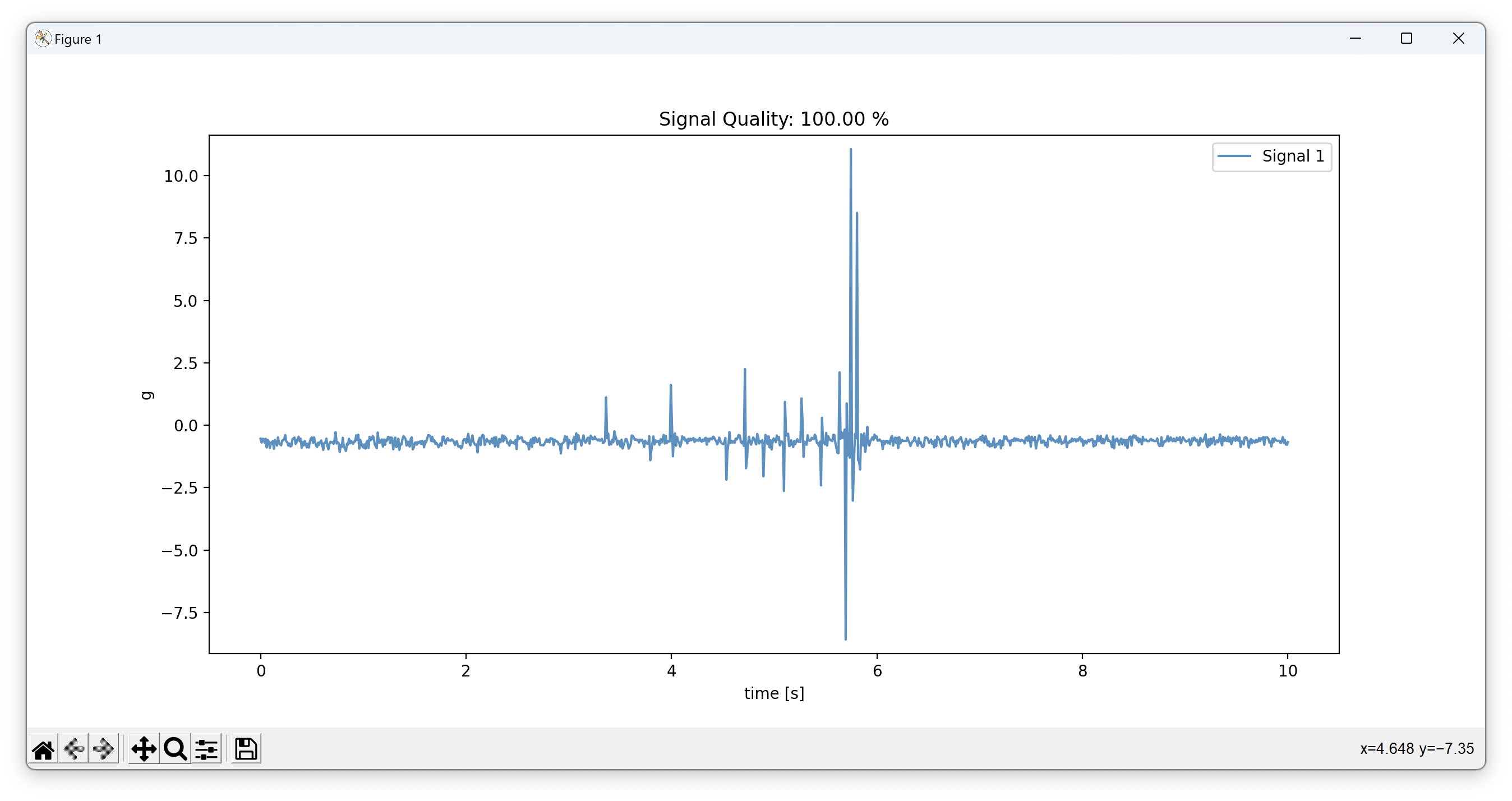
will show the sensor data. To stop the data acquisition, click the close button on the top of the graph. For more information on how to use ICOc and the test suite, please take a look at the section “Tutorials”.
1.3.3 Measurement Data
Note: ICOc assumes that the sensor device always measures acceleration data in multiples of the gravity of earth, commonly referred as \(g\) or \(g_0\). While this is true for most of the sensor hardware (such as STHs), some sensor devices measure other values, e.g. force or temperature. Even in this case the measurement software will (incorrectly) convert the data into multiples of \(g\). We are working on adding support for configuring the sensor type in the firmware and ICOc to fix this issue.
The ICOc script stores measured acceleration values in HDF5 files. By default these files will be stored in the root of the repository with
- a name starting with the text
Measurement - followed by a date/time-stamp,
- and the extension
.hdf5.
To take a look at the measurement data you can use the tool HDFView. Unfortunately you need to create a free account to download the program. If you do not want to register, then you can try if one of the accounts listed at BugMeNot works. Another option is to download the application from here. Just click on the folder for the latest version of the application (hdfview-…) and afterwards on the folder bin to see a list of compressed binaries (.zip & .tar.gz) for the different supported operating systems.
The screenshot below shows a measurement file produced by ICOc:
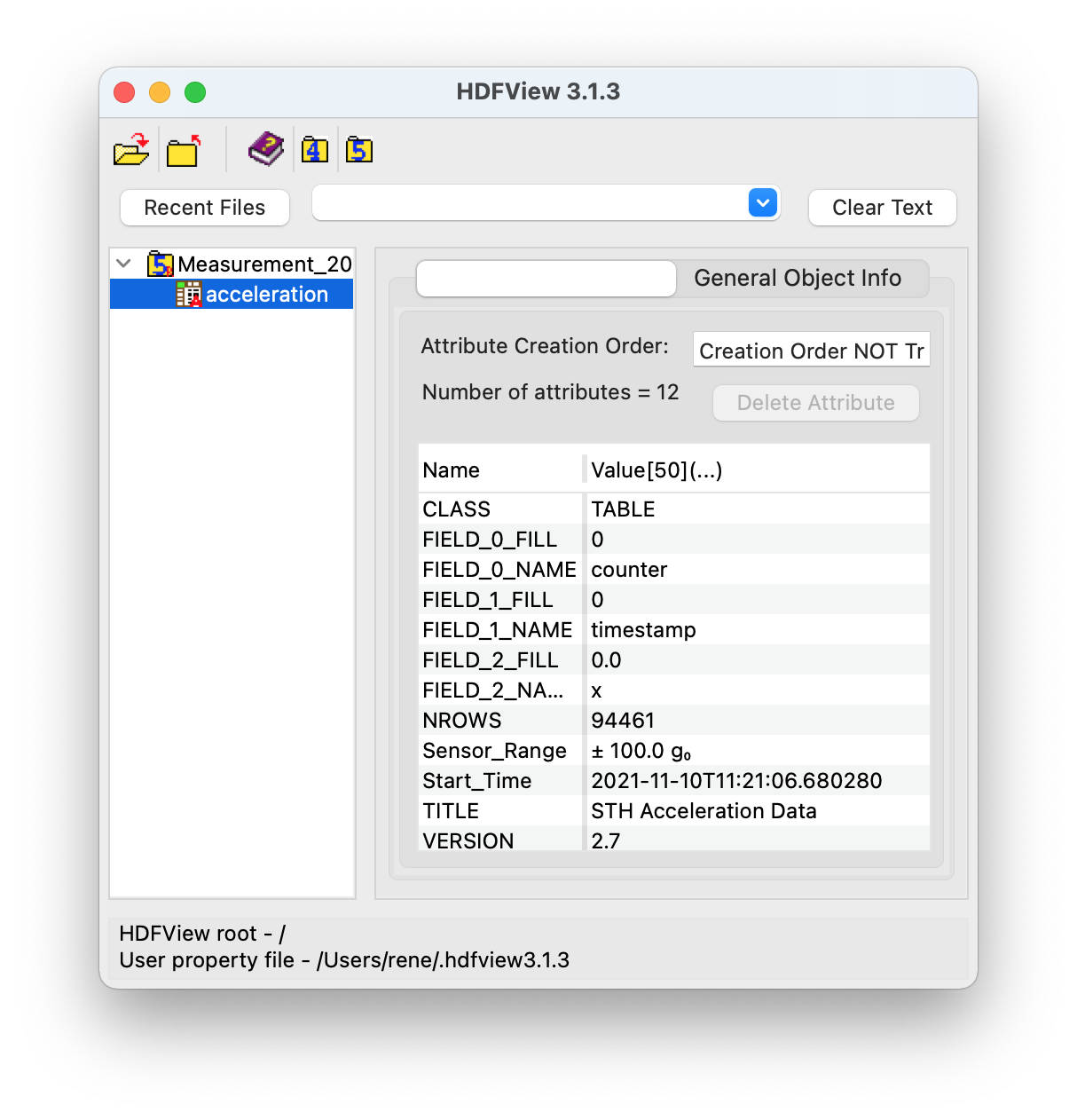
As you can see the table with the name acceleration stores the acceleration data. The screenshot above displays the metadata of the table. The most important meta attributes here are probably:
Start_Time, which contains the start time of the measurement run in ISO format, andSensor_Range, which specifies the range of the used acceleration sensor in multiples of earth’s gravitation (g₀ ≅ 9.81 m/s²).
After you double click on the acceleration table on the left, HDFView will show you the actual acceleration data:
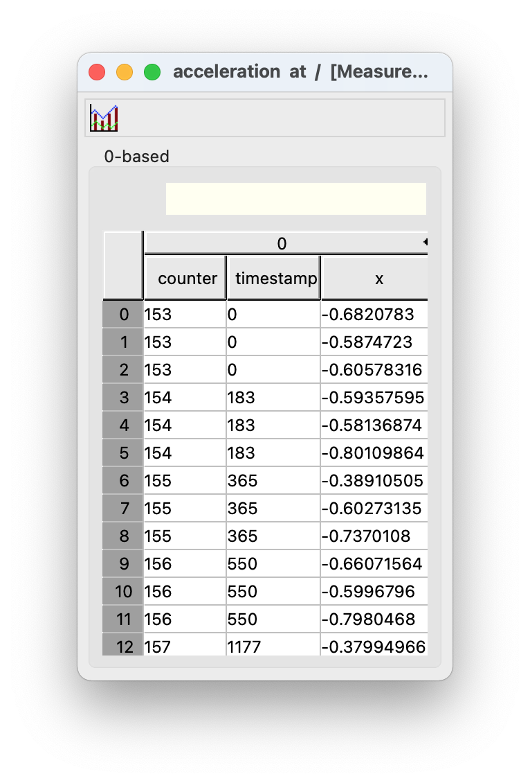
As you can infer from the x column above the table shows the acceleration measurement data (in multiples of g₀) for a single axis. The table below describes the meaning of the columns:
| Column | Description | Unit |
|---|---|---|
| counter | A cyclic counter value (0–255) sent with the acceleration data to recognize lost packets | – |
| timestamp | The timestamp for the measured value in microseconds since the measurement start | μs |
| x | Acceleration in the x direction as multiples of earth’s gravitation | g₀ (≅ 9.81 m/s²) |
Depending on your sensor and your settings the table might also contain columns for the y and/or z axis.
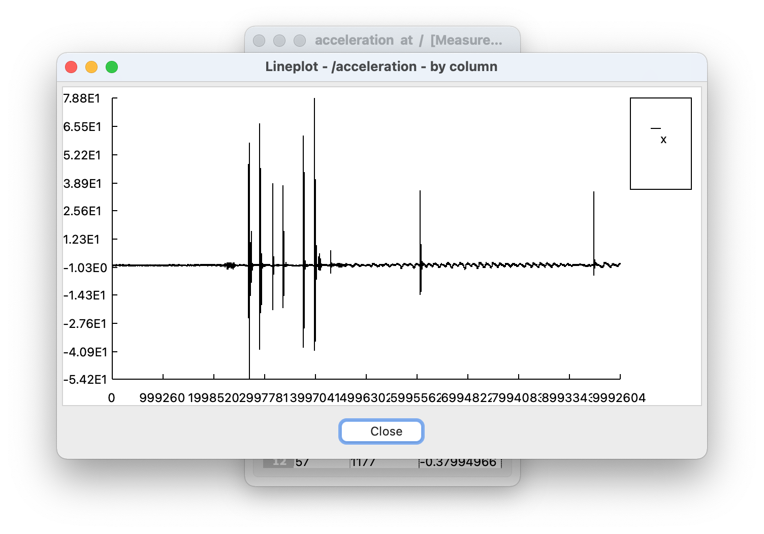
If you want you can also use HDFView to print a simple graph for your acceleration data. To do that:
- Select the values for the the ordinate (e.g. click on the x column to select all acceleration data for the x axis)
- Click on the graph icon in the top left corner
- Choose the data for the abscissa (e.g. the timestamp column)
- Click on the “OK” button
The screenshot below shows an example of such a graph:
For a more advanced analysis of the data files you can use our collection of measurement utility software ICOlyzer.
1.3.3.1 Adding Custom Metadata
Sometimes you also want to add additional data about a measurement. To do that you can also use HDFView. Since the tool opens files in read-only mode by default you need to change the default file access mode to “Read/Write” first:
- Open HDFView
- Click on “Tools” → “User Options”
- Select “General Settings”
- Under the text “Default File Access Mode” choose “Read/Write”
- Close HDFView
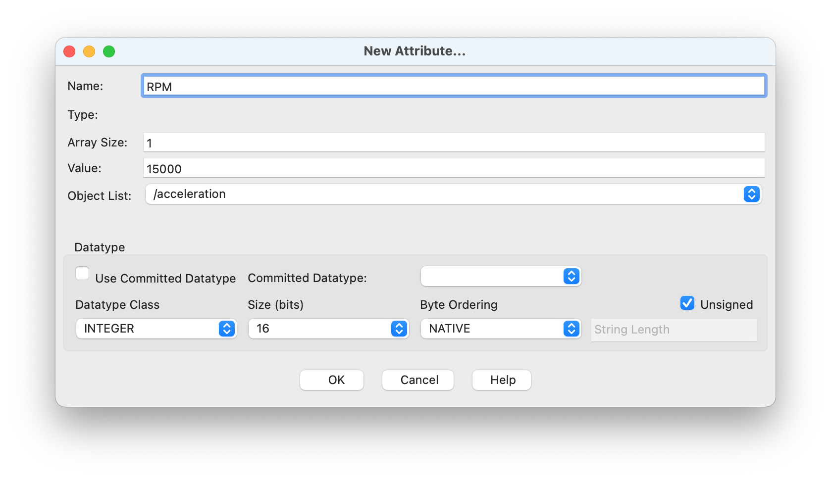
Now you should be able to add and modify attributes. For example, to add a revolutions per minute (RPM) value of 15000 you can use the following steps:
- Open the measurement file in HDFView
- Click on the table “acceleration” in the left part of the window
- In the tab “Object Attribute Info” on the right, click on the button “Add attribute”
- Check that “Object List” contains the value “/acceleration”
- Enter the text “RPM” in the field “Name”
- In the field “Value” enter the text “15000”
- The “Datatype Class” should be set to “INTEGER”
- For the size (in bits) choose a bit length that is large enough to store the value. In our example everything equal to or larger than 16 bits should work.
- Optionally you can also check “Unsigned”, if you are sure that you only want to store positive values
- Click the button “OK”
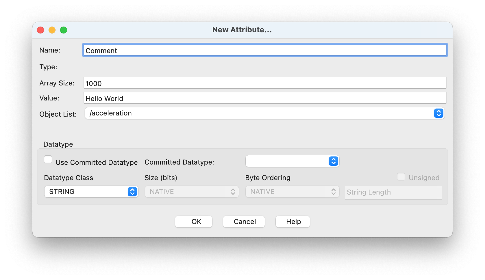
Sometimes you also want to add some general purpose data. For that you can use the “STRING” datatype class. For example, to store the text “hello world” in an attribute called “Comment” you can do the following
- Repeat steps 1. – 4. from above
- Choose “STRING” as “Datatype Class”
- Under “Array Size” choose a length that is large enough to store the text such as “1000” (every size larger than or equal to 11 characters should work)
- Click the button “OK”
If you want you can also add multiline text. Since you can not add newlines using ⏎ in HDFView directly, we recommend you open your favorite text editor to write the text and then copy and paste the text into the value field. HDFView will only show the last line of the pasted text. However, after you copy and paste the text into another program you will see that HDFView stored the text including the newlines.
1.3.4 Changing Configuration Values
Note: If you only use the
icoccommand line tool, then you most probably do not need to change the configuration at all.
All configuration options are currently stored in YAML files (handled by the configuration library Dynaconf). The default values are stored inside the package itself. If you want to overwrite or extend these values you should create a user configuration file. To do that you can use the command:
which will open the the user configuration in your default text editor. You can then edit this file and save your changes to update the configuration. For a list of available options, please take a look at the default configuration. Please make sure to not make any mistakes when you edit this file. Otherwise (parts of) the ICOc commands will not work, printing an error message about the (first) incorrect configuration value.
1.3.4.1 Adding the Path to Simplicity Commander on Linux
Open the user configuration file in your default text editor using the command line tool
icon:Add the path to Simplicity commander (e.g.
/opt/Simplicity Commander/commander/) to the listcommands→path→linux:Note: Keys (such as
commands,pathandlinux) in the example above are case-insensitive in Dynaconf, e.g. it does not matter if you usecommandsorCOMMANDSin the example above.Store the modified configuration file
1.3.4.2 Setting up the Test Environment
Open the user configuration in your default text editor:
If you never edited the configuration before, then the displayed text should be the same as in the file linked here.
Change the programming board serial number, to the serial number of your programming board (shown on the bottom of the display):
Change the production date to the one of your PCB in ISO date format:
Change the user name to the name of the person that runs the test:
Change the holder type (only relevant for the test report):
Change the holder name (Bluetooth advertisement name) to the one of your sensor device. If your are not sure about the name you can use the
iconoricoccommand line tool to determine the name. The STH and SMH tests use this value to connect to the device.Update the serial number of the sensor device. The STH and SMH tests change the sensor device Bluetooth advertisement name to this value, after the EEPROM (part of the) test was executed, if the state value is set to
Epoxied.Change the state value to
Bare PCB, if the sensor device test (SMH/STH test) should flash the sensor device or toEpoxiedif the test should not flash the sensor device.
2 Tutorials
2.1 Sensor Device Renaming
Please start ICOc:
The text based interface will show you a selection of the available devices:
                ICOc

       Name      Address            RSSI
———————————————————————————————————————————————
    1: Serial    08:6b:d7:01:de:81  -44 dBm

┌──────────────────────────────┐
│ 1-9: Connect to STH          │
│                              │
│   f: Change Output File Name │
│   n: Change STH Name         │
│                              │
│   q: Quit ICOc               │
└──────────────────────────────┘
Choose the STH you want to rename by entering the number to the left of the device (here
1). To confirm your selection press the return key ⮐.Now the menu should look like this:
                ICOc
STH “Serial” (08:6b:d7:01:de:81)
————————————————————————————————

Hardware Version      1.4.0
Firmware Version      2.1.10
Firmware Release Name Tanja
Serial Number         –

Supply Voltage        3.16 V
Chip Temperature      26.2 °C

Run Time              ∞ s

Prescaler             2
Acquisition Time      8
Oversampling Rate     64
⇒ Sampling Rate       9524
Reference Voltage     VDD

Sensors               M1: S1

┌───────────────────────────┐
│ s: Start Data Acquisition │
│                           │
│ n: Change STH Name        │
│ r: Change Run Time        │
│ a: Configure ADC          │
│ p: Configure Sensors      │
│ O: Set Standby Mode       │
│                           │
│ q: Disconnect from STH    │
└───────────────────────────┘
Press the button
nto change the name.Enter the new device name.
New STH name (max. 8 characters): BlubbConfirm the name with the return key ⮐.
The interface should now show you the menu of step 3. To disconnect from the holder press e.
Now you see the main menu of ICOc. The STH will show up under the name you used in step 4.
To exit ICOc, please use the key q.
2.2 Command Line Usage of ICOc
The ICOc program accepts optional command line arguments at startup. This way you can set default values for often used options. If you specify
- the name or
- Bluetooth address
of a sensor device, then you can even use ICOc without any user interaction, since in this case the program will immediately connect to the specified device and start the measurement process.
2.2.1 Available Options
To show the available command line options you can use the option -h:
which should show you the following output:
usage: icoc [-h] [-b BLUETOOTH_ADDRESS | -n [NAME]] [-f FILENAME] [-r SECONDS] [-1 [FIRST_CHANNEL]] [-2 [SECOND_CHANNEL]] [-3 [THIRD_CHANNEL]] [-s 2–127] [-a {1,2,3,4,8,16,32,64,128,256}]
            [-o {1,2,4,8,16,32,64,128,256,512,1024,2048,4096}] [-v {1V25,Vfs1V65,Vfs1V8,Vfs2V1,Vfs2V2,2V5,Vfs2V7,VDD,5V,6V6}] [--log {debug,info,warning,error,critical}]

Configure and measure data with the ICOtronic system

options:
  -h, --help            show this help message and exit

Connection:
  -b BLUETOOTH_ADDRESS, --bluetooth-address BLUETOOTH_ADDRESS
                        connect to device with specified Bluetooth address (e.g. “08:6b:d7:01:de:81”)
  -n [NAME], --name [NAME]
                        connect to device with specified name

Measurement:
  -f FILENAME, --filename FILENAME
                        base name of the output file (default: Measurement)
  -r SECONDS, --run-time SECONDS
                        run time in seconds (values equal or below “0” specify infinite runtime) (default: 0)
  -1 [FIRST_CHANNEL], --first-channel [FIRST_CHANNEL]
                        sensor channel number for first measurement channel (1 - 255; 0 to disable) (default: 1)
  -2 [SECOND_CHANNEL], --second-channel [SECOND_CHANNEL]
                        sensor channel number for second measurement channel (1 - 255; 0 to disable) (default: 0)
  -3 [THIRD_CHANNEL], --third-channel [THIRD_CHANNEL]
                        sensor channel number for third measurement channel (1 - 255; 0 to disable) (default: 0)

ADC:
  -s 2–127, --prescaler 2–127
                        Prescaler value (default: 2)
  -a {1,2,3,4,8,16,32,64,128,256}, --acquisition {1,2,3,4,8,16,32,64,128,256}
                        Acquisition time value (default: 8)
  -o {1,2,4,8,16,32,64,128,256,512,1024,2048,4096}, --oversampling {1,2,4,8,16,32,64,128,256,512,1024,2048,4096}
                        Oversampling rate value (default: 64)
  -v {1V25,Vfs1V65,Vfs1V8,Vfs2V1,Vfs2V2,2V5,Vfs2V7,VDD,5V,6V6}, --voltage-reference {1V25,Vfs1V65,Vfs1V8,Vfs2V1,Vfs2V2,2V5,Vfs2V7,VDD,5V,6V6}
                        Reference voltage (default: VDD)

Logging:
  --log {debug,info,warning,error,critical}
                        Minimum level of messages written to log (default: info)
All options below the section “Measurement” and “ADC” in the help output of ICOc allow you to change a specific configuration value before you start ICOc.
2.2.2 Channel Selection
To enable the measurement for the first (“x”) channel and second (“y”) channel of an “older” STH (Firmware 2.x, BGM113 chip) you can use the following command:
Here 0 indicates that you want to disable the channel, while a positive number (such as 1) specifies that the measurement for the channel should take place. Since the default value
- for the option
-1is already1, and - for the option
-3is already0
you can also leave out these options to arrive at the shorter command:
icoc -2 1Note: Due to a problem in the current firmware the amount of paket loss is much higher, if you
- use the standard ADC configuration values, and
- enable data transmission for exactly 2 (channels).
We strongly recommend you use either one or three channels.
For newer STH versions (Firmware 3.x, BGM121 chip) or SMHs (Sensory Milling Heads) you can also change the hardware/sensor channel for the first, second and third measurement channel. For example, to select
- hardware channel 8 for the first measurement channel
- hardware channel 1 for the second measurement channel, and
- hardware channel 3 for the third measurement channel
you can use the following command:
Note: If you connect to an older STH using the command above, then the command would just enable the measurement for all three measurement channels, but not change the selected hardware channel.
If you just want to enable/set a measurement channel and use the hardware channel with the same number you can also just leave the argument for the specific measurement channel empty. For example, to use
- hardware channel 1 for measurement channel 1,
- hardware channel 2 for measurement channel 2, and
- hardware channel 3 for measurement channel 3
you can use the following command:
or even shorter, since the default value for measurement channel 1 is hardware channel 1:
icoc -2 -32.2.3 Changing the Run Time
To change the run time of the measurement you can use the option -r, which takes the runtime in seconds as argument. The command
for example, would change the runtime to 300 seconds (5 minutes).
2.2.4 Start the Measurement
If you specify one of the options
-b/--bluetooth-addressor-n/--name
then ICOC will try to connect immediately to the specified device and start the measurement run. For example, to acquire acceleration data from the device with the (Bluetooth advertisement) name “Blubb” you can use the following command:
To read acceleration values for 5 seconds from the device with the Bluetooth address 08:6b:d7:01:de:81 you can use the following command:
2.2.5 Changing the Logging Level
By default ICOc only writes log messages of level INFO or higher. In some situations, for example when ICOc behaves incorrectly, you might want to set a lower level. You can do that using the option --log. For example, to activate logging of level WARNING and higher when you start ICOc you can use the following command:
The different logs for ICOc are stored in the user log directory in the following files:
cli.log: Log messages of ICOcnetwork.log: Log messages of CAN network classplotter.log: Log messages of plotter (process for measurement graph)
To determine the user log directory on your machine you can use the following Python code:
2.2.6 Changing the Reference Voltage
For certain sensor devices you have to change the reference voltage to retrieve a proper measurement value. For example, STHs that use a ± 40 g acceleration sensor (ADXL356) require a reference voltage of 1.8 V instead of the usual supply voltage (VDD) of 3.3 V. To select the correct reference voltage for these devices at startup use the option -v Vfs1V8:
2.2.7 Changing the Sampling Rate
If you want to change the sampling rate you can do that by changing the parameters of the ADC. There are 3 parameters which influence the sampling rate.
- Prescaler (Prescaler used by the ADC to get the sample points)
- Acquisition Time (Time the ADC holds a value to get a sampling point)
- Oversampling Rate (Oversampling rate of the ADC)
The formula which can be used to calculate the sampling rate can be found in the documentation of the CAN commands.
2.3 ICOn CLI Tool
One issue of the ICOc (command line tool) is that it only works on Windows. Another problem is that it requires a CAN adapter from PEAK-System.
To improve this situation we offer an API (Application Programming Interface) based on python-can, which works on
- Linux,
- macOS, and
- Windows
and should (at least in theory) support the same CAN hardware as python-can. You can access most of this API using the “new” Network class.
We also offer a (currently very limited) CLI tool based on this API called ICOn. The text below describes how you can use this tool.
2.3.1 Listing Available Sensor Devices
To print a list of all available sensor devices please use the subcommand list:
2.3.2 Collecting Measurement Data
To collect and store measurement data from an STH you can uses the subcommand measure:
By default the command will collect streaming data for 10 seconds for the first measurement channel and store the data as Measurement.hdf5 in the current working directory. You can change the default measurement duration using the option -t/--time. For example to collect measurement data for 1.5 seconds from the STH with the name Test-STH use the command:
2.3.3 Renaming a Sensor Device
To change the name of a sensor you can use the subcommand rename. For example to change the name of the sensor device with the Bluetooth MAC address 08-6B-D7-01-DE-81 to Test-STH use the following command:
For more information about the command you can use the option -h/--help:
2.3.4 Opening the User Configuration
To open the user configuration file, you can use the subcommand config:
If the file does not exist yet, then it will be created and filled with the content of the default user configuration. For more information on how to change the configuration, please take a look here.
2.3.5 STU Commands
To list all available STU subcommands, please use the option -h (or --help):
2.3.5.1 Enable STU OTA Mode
To enable the Bluetooth advertising of the STU and hence the “over the air” firmware update, please run the following command:
2.4 Production Tests
This tutorial lists the usual steps to test a sensory holder assembly or a sensory tool holder.
2.4.1 General
To run the production tests for one of the ICOtronic devices, please execute one of the following commands:
| Device | Command |
|---|---|
| Stationary Transceiver Unit (STU) | test-stu |
| Sensory Holder Assembly (SHA), Sensory Tool Holder (STH) | test-sth |
| Sensory Milling Head (SMH) | test-smh |
For a list of available command line options, please use the option -h after one of the commands e.g.:
2.4.1.1 Specific Tests
To only run a single test you need the specify its name. For example, to run the test test__firmware_flash of the STU you can use the following command:
You can also run specific tests using pattern matching. To do that use the command line option -k. For example to run the firmware flash and the connection test of the STH test you can use the command:
which executes all tests that contain the text flash or connection.
2.4.2 STH
The text below gives you a more detailed step-by-step guide on how to run the tests of the STH.
Note: You can skip this step, if you do not want to run the flash test. To skip the flash test, please set
sth→statusin the configuration toEpoxied.Please create a directory called
Firmwarein the current user’sDocumentsdirectory (~/Documents).Note: To open the user’s home directory on Windows you can use the following command in (Windows) Terminal:
Then put the current version of the STH firmware into this directory. Afterwards the directory and file structure should look like this:
~
└── Documents
        └── Firmware
                └── manufacturingImageSthv2.1.10.hex
As alternative to the steps above you can also change the variable
sth→firmware→location→flashin the configuration to point to the firmware that should be used for the flash test.Make sure that the configuration values are set correctly. You probably need to change at least the following variables:
Name: Please change the Bluetooth advertisement name (
sth→name) to the name of the STH you want to test.Serial Number of Programming Board: Please make sure, that the variable
sth→programming board→serial numbercontains the serial number of the programming board connected to the STH. This serial number should be displayed on the bottom right of the LCD on the programming board.
Please open your favorite Terminal application and execute, the STH test using the command
test-sth. For more information about this command, please take a look at the section “General” above.Please note, that the test will rename the tested STH
to a Base64 encoded version of the Bluetooth MAC address, if
sth→statusis set toBare PCB, orto the serial number (
sth→programming board→serial number), if you set the status toEpoxied.
2.4.3 SMH
The preparation steps for the SMH test are very similar to the ones of the STH test.
Please make sure that the config value that stores the SMH firmware filepath (
smh→firmware→location→flash) points to the correct firmware. If you have not downloaded a firmware image for the SMH you can do so here.Check that the configuration values like SMH name (
smh→name) and programming board serial number (smh→programming board→serial number) are set correctly.Please execute the test using the following command:
2.4.4 STU
The following description shows you how to run the STU tests.
Note: You can skip this step, if you do not want to run the flash test.
Please take a look at step 1 of the description for the STH test and replace every occurrence of STH (or
sth) with STU (orstu).Note: The STU test always uploads the flash file to the board, i.e. the setting
stu→statusis not read/used by the STU tests.In the end of this step the directory structure should look like this:
~
└── Documents
       └── Firmware
              └── manufacturingImageStuv2.1.10.hex
You can find the current version of the STU firmware here.
Please take a look at the section “General” to find out how to execute the production tests for the STU. If you want to run the connection and EEPROM test (aka all tests except the flash test, i.e. the EEPROM and connection test), then please execute the following command:
2.4.5 Firmware Versions
The (non-exhaustive) table below shows the compatible firmware for a certain device. The production tests assume that you use firmware that includes the bootloader.
| Device | Hardware Version | Microcontroller | Firmware |
|---|---|---|---|
| STH | 1.3 |
BGM113 | • Version 2.1.10 |
| STH | 2.2 |
BGM123 | • Aladdin |
| SMH | 2.1 |
BGM121 | • Version 3.0.0 • Version E3016 Beta |
2.5 Verification Tests
2.5.1 Preparation
- The tests assume that the name of the STH is stored in
sth→namein the configuration. - Some of the STH tests assume that you connected the SHA/STH or STU via the programming cable. Please do that, since otherwise these tests will fail.
2.5.2 Execution
To run the verification tests for the STH, please enter the following command:
To execute the STU verification tests, you can use the command:
Please note that while most of the tests should run successfully, if you use working hardware and firmware, some of them might fail occasionally. In this case please rerun the specific test using the option -k and specifying a text that matches the name of the test. For example, to return the STH test test0107BlueToothConnectMin you can use the following command:
Note: If you want to stop the test while it is running, but Ctrl + C does not terminate the test as you expected, then you can use the command:
to stop all running Python interpreters and hence also the
test-sth-verificationscript.
2.5.3 Problematic Tests
The tables below contains a list of tests that failed using a working SHA/STH and STU before. It should provide you with a good overview of which of the verification tests might fail, even if the hardware and firmware works correctly.
2.5.3.1 STH
| Date | Failed Tests |
|---|---|
| 2021-09-29 | • test0107BlueToothConnectMin • test0332SignalIndicatorsAccZ • test0334SignalIndicatorsMulti • test0345MixedStreamingAccYZVoltBat |
| 2021-09-30 | • test0332SignalIndicatorsAccZ • test0334SignalIndicatorsMulti • test0345MixedStreamingAccYZVoltBat |
| 2021-09-30 | • test0332SignalIndicatorsAccZ • test0334SignalIndicatorsMulti • test0532MessageCountersAccZBattery |
| 2021-10-05 | • test0334SignalIndicatorsMulti • test0347StreamingAccXSingleBattery |
| 2021-10-06 | • test0109BlueToothRssi • test0334SignalIndicatorsMulti |
| 2021-10-06 | • test0107BlueToothConnectMin • test0334SignalIndicatorsMulti • test0345MixedStreamingAccYZVoltBat |
| 2021-10-07 | • test0107BlueToothConnectMin • test0332SignalIndicatorsAccZ • test0334SignalIndicatorsMulti • test0344MixedStreamingAccXYVoltBat • test0345MixedStreamingAccYZVoltBat |
| 2021-10-11 | • test0015PowerConsumptionEnergySaveMode2 • test0016PowerConsumptionEnergySaveModeAdv4000ms • test0332SignalIndicatorsAccZ • test0334SignalIndicatorsMulti • test0508AdcConfigSingle |
| 2021-10-12 | • test0332SignalIndicatorsAccZ • test0334SignalIndicatorsMulti • test0532MessageCountersAccZBattery |
| 2021-10-13 | • test0332SignalIndicatorsAccZ • test0334SignalIndicatorsMulti • test0508AdcConfigSingle • test0509AdcConfigDouble • test0510AdcConfigTripple • test0525MessageCounterAccZ |
| 2021-12-09 | • test0107BlueToothConnectMin • test0510AdcConfigTripple • test0523MessageCounterAccX • test0527MessageCounterAccXZ • test0529MessageCounterAccXYZ |
| 2021-12-14 | • test0107BlueToothConnectMin |
| 2022-05-17 | • test0015PowerConsumptionEnergySaveMode2 • test0016PowerConsumptionEnergySaveModeAdv4000ms • test0334SignalIndicatorsMulti • test0344MixedStreamingAccXYVoltBat • test0357StreamingAccXYSingleBattery |
3 Code Examples
For information on how to write your own code including sample code please take a look at the API documentation.
4 Virtualization
You can also use (parts of) ICOc with various virtualization software. For that to work you have to make sure that (at least) the PEAK CAN adapter is attached to the virtual guest operating system. For some virtualization software you might have to install additional software for that to work. For example, VirtualBox requires that you install the VirtualBox Extension Pack before you can use USB 2 and USB 3 devices.
Note: Please be advised that the VirtualBox Extension Pack is paid software even though you can download and use it without any license key. Oracle might come after you, if you do not pay for the license, even if you use the Extension Pack in an educational setting.
The table below shows some of the virtualization software we tried and that worked (when we tested it).
| Virtualization Software | Host OS | Host Architecture | Guest OS | Guest Architecture | Notes |
|---|---|---|---|---|---|
| Parallels Desktop | macOS | x64 |
Ubuntu 20.04 | x64 |
|
| Parallels Desktop | macOS | x64 |
Windows 10 | x64 |
|
| Parallels Desktop | macOS | ARM64 |
Fedora 36 | ARM64 |
|
| Parallels Desktop | macOS | ARM64 |
Windows 11 | ARM64, x64 |
JLink (and hence Simplicity Commander) only works with programming adapters that support WinUSB |
| VirtualBox | macOS | x64 |
Windows 10 | x64 |
|
| VirtualBox | Windows | x64 |
Fedora 36 | x64 |
|
| WSL 2 | Windows | x64 |
Ubuntu 22.04 | x64 |
4.1 Windows Subsystem for Linux 2
Using ICOc in the WSL 2 currently requires using a custom Linux kernel. We would not recommend using ICOc with this type of virtualization software, since the setup requires quite some amount of work and time. Nevertheless the steps below should show you how you can use the PEAK CAN adapter and hence ICOc with WSL 2.
Install WSL 2 (Windows Shell):
wsl --installInstall Ubuntu 22.04 VM (Windows Shell):
Open the Ubuntu 22.04 application
- Choose a user name
- Choose a password
Execute the following commands in a Powershell session
wsl --setdefault Ubuntu-22.04
wsl --set-version Ubuntu-22.04 2
The second command might fail, if
Ubuntu-22.04already uses WSL 2. In this case please just ignore the error message.
-
Windows Shell:
Note: Please replace
<user>with your (Linux) username (e.g.rene)cd ~/Documents mkdir WSL cd WSL wsl --export Ubuntu-22.04 CANbuntu.tar wsl --import CANbuntu CANbuntu CANbuntu.tar wsl --distribution CANbuntu --user <user>Linux Shell:
sudo apt update
sudo apt upgrade -y
sudo apt install -y bc build-essential flex bison libssl-dev libelf-dev \
                    libncurses-dev autoconf libudev-dev libtool dwarves
cd ~
git clone https://github.com/microsoft/WSL2-Linux-Kernel.git
cd WSL2-Linux-Kernel
uname -r # 5.15.74.2-microsoft-standard-WSL2 → branch …5.15.y
git checkout linux-msft-wsl-5.15.y
cat /proc/config.gz | gunzip > .config
make menuconfig
Make sure the following features are enabled:
Device Drivers→USB SupportDevice Drivers→USB Support→USB announce new devicesDevice Drivers→USB Support→USB Modem (CDC ACM) supportDevice Drivers→USB Support→USB/IPDevice Drivers→USB Support→USB/IP→VHCI HCDDevice Drivers→USB Support→USB Serial Converter SupportDevice Drivers→USB Support→USB Serial Converter Support→USB FTDI Single port Serial Driver
Enable the following features:
Networking support→CAN bus subsystem supportNetworking support→CAN bus subsystem support→Raw CAN ProtocolNetworking support→CAN bus subsystem support→CAN device drivers→Virtual Local CAN InterfaceNetworking support→CAN bus subsystem support→CAN device drivers→Serial / USB serial CAN Adaptors (slcan)Networking support→CAN bus subsystem support→CAN device drivers→CAN USB Interfaces→PEAK PCAN-USB/USB Pro interfaces for CAN 2.0b/CAN-FD
Save the modified kernel configuration.
Linux Shell:
Install
usbipd-win(Linux Shell):Copy image (Linux Shell):
Note: Please replace
<user>with your (Windows) username (e.g.rene)Create
.wslconfigin (root of) Windows user directory and store the following text:Note: Please replace
<user>with your (Windows) username (e.g.rene)Set default distribution (Windows Shell)
Shutdown and restart WSL (Windows Shell):
wsl --shutdown
wsl -d CANbuntu --cd "~"
Change default user of WSL distro (Linux Shell)
sudo nano /etc/wsl.confInsert the following text:
Note: Please replace
<user>with your (Windows) username (e.g.rene)Save the file and exit
nano:- Ctrl + O
- ⏎
- Ctrl + X)
Restart WSL: See step
8Install
usbipd(Windows Shell):winget install usbipdAttach CAN-Adapter to Linux VM (Windows Shell)
usbipd wsl list
# …
# 5-3    0c72:0012  PCAN-USB FD                      Not attached
# …
usbipd wsl attach -d CANbuntu --busid 5-3
usbipd wsl list
# …
# 5-3    0c72:0012  PCAN-USB FD                      Attached - CANbuntu
# …
Check for PEAK CAN adapter in Linux (Optional, Linux Shell):
Add virtual link for CAN device (Linux Shell)
Note: If the commands above fail with the error message:
RTNETLINK answers: Connection timed out
then please disconnect and connect the USB CAN adapter. After that attach it to the Linux VM again (see step
12).Install
pip(Linux Shell):Install ICOc (Linux Shell)
Run a script to test that everything works as expected (Linux Shell)
If the command above fails with the message
Command 'icon' not found…then you might have to logout and login into the WSL session again before you execute
icon listagain.
Notes:
- You only need to repeat steps
12: attach the CAN adapter to the VM in Windows and14: create the link for the CAN device in Linuxafter you set up everything properly once.
- Unfortunately configuring the CAN interface automatically does not seem to work (reliably) on WSL yet
4.1.1 Installing/Using Simplicity Commander
Download and unpack Simplicity Commander (Linux Shell)
sudo apt install -y unzip
mkdir -p ~/Downloads
cd ~/Downloads
wget https://www.silabs.com/documents/public/software/SimplicityCommander-Linux.zip
unzip SimplicityCommander-Linux.zip
cd SimplicityCommander-Linux
tar xf Commander-cli_linux_x86_64*.tar.bz
mkdir -p ~/Applications
mv commander-cli ~/Applications/commander
ln -s ~/Applications/commander/commander-cli ~/Applications/commander/commander
# Fix J-Link connection
# https://wiki.segger.com/J-Link_cannot_connect_to_the_CPU
sudo cp ~/Applications/commander/99-jlink.rules /etc/udev/rules.d/
Add
commanderbinary to path (Linux Shell)Open
~/.profileinnano:Add the following text at the bottom:
Save your changes
Restart WSL
Connect programming adapter to Linux (Windows Shell)
usbipd wsl list
# …
# 5-4    1366:0105  JLink CDC UART Port (COM3), J-Link driver Not attached
# …
usbipd wsl attach --busid 5-4
Check if
commanderJLink connection works without usingsudo(Linux Shell)Notes:
Please replace
<serialnumber>with the serial number of your programming board (e.g.440069950):If the command above fails with the error message:
error while loading shared libraries: libGL.so.1: cannot open shared object file…then you need to install
libgl1:
4.1.2 Run Tests in WSL
Note: The tests use the command-line xdg-open. For the tests also work on Linux, then you need to install the Python package xdg-open-wsl:
pip3 install --user git+https://github.com/cpbotha/xdg-open-wsl.gitStart WSL (Windows Shell)
Connect programming/CAN adapter to Linux (Windows Shell):
Configure CAN interface (Linux Shell):
Run tests (Linux Shell):
5 Containerization
5.1 Docker on Linux
The text below shows how you can use (code of) the new Network class in a Docker container on a Linux host. The description on how to move the interface of the Docker container is an adaption of an article/video from the “Chemnitzer Linux-Tage”.
5.1.1 Creating a Docker Image
To create a Docker image that contains ICOc just install the package with pip inside your Dockerfile. We recommend that you use a virtual environment to install the package. For an example, please take a look at the Dockerfile in the folder Docker.
5.1.2 Building the Docker Image
If you do not want to create a Dockerfile yourself, you can build an image based on our Docker example file:
5.1.3 Using ICOc in the Docker Container
Run the container (Terminal 1)
Open a new terminal window
Open a shell in the Docker container
Move the CAN interface into the network space of the Docker container (Terminal 2)
export DOCKERPID="$(docker inspect -f '{{ .State.Pid }}' icoc)"
sudo ip link set can0 netns "$DOCKERPID"
sudo nsenter -t "$DOCKERPID" -n ip link set can0 type can bitrate 1000000
sudo nsenter -t "$DOCKERPID" -n ip link set can0 up
Note: Alternatively you can also add the option
--network hostto the Docker command from step 1. Please check out the Docker documentation to learn more about the consequences of using this option.Run a test command in Docker container (Terminal 1) e.g.:
6 Scripts
After you installed the ICOc package various helper scripts are available:
convert-base64-mac: Utility to convert a Base64 encoded 8 character text into a Bluetooth MAC addressconvert-mac-base64: Convert Bluetooth MAC address into a (Base64) encoded 8 character stringcheck-eeprom: Write a byte value into the cells of an EEPROM page an check how many of the values are read incorrectly after an reseticoc: Controller and measurement software for the ICOtronic systemicon: Controller software for the ICOtronic systemtest-smh: Test code for the SMHtest-sth: Test code for the STH/SHAtest-stu: Test code for the STU
6.1 EEPROM Check
The script check-eeprom connects to an STH using its MAC address. Afterwards it writes a given byte value (default: 10) into all the cells of an EEPROM page. It then resets the STH, connects again and shows the amount of incorrect EEPROM bytes. It repeats the last steps 5 times before it prints all values in the EEPROM page.
The command below shows how to execute the EEPROM check for the STH with MAC address 08:6b:d7:01:de:81:
You can specify the value that should be written into the EEPROM cells using the option --value:
6.2 ICOc
The command icoc calls ui.py. All command line arguments to the script will be directly forwarded to ui.py. For example, to read acceleration data for 10 seconds from the STH with the (Bluetooth advertisement) name CGvXAd6B, you can use the following command:
6.3 ICOn
The command ICOn uses the new Network class (based on python-can) to communicate with the ICOtronic system. Compared to ICOc the script currently offers very limited functionality. However, in the future most of the functionality from ICOc should be integrated into this new command line tool. A big advantage of ICOn compared to ICOc is that the command also works on Linux and macOS. For more information, please take a look here.
6.4 MAC Address Conversion
The utility convert-mac-base64 returns the Base64 encoded version of a MAC address. We use the encoded addresses as unique Bluetooth advertisement name for the STH (or SHA). Unfortunately we can not use the MAC address directly because the maximum length of the name is limited to 8 characters. To decode the Base64 name back into a Bluetooth address you can use the script convert-base64-mac.
6.5 Test-STH
The command test-sth is a command that executes the tests for the STH (sth.py). All command line arguments of the wrapper will be forwarded to sth.py.
7 Development
7.1 Install
You can use the instructions below, if you want to work on the code of ICOc, i.e. add additional features or fix bugs.
Clone the repository to a directory of your choice. You can either use the command line tool
git:or one of the many available graphical user interfaces for Git to do that.
Install ICOc in “developer mode”
Change your working directory to the (root) directory of the cloned repository
Install ICOc:
Notes:
- The command above will install the repository in “editable mode” (
-e), meaning that a command such asicocwill use the current code inside the repository. - The command also installs
- development (
dev) and - test (
test) dependencies
- development (
- The command above will install the repository in “editable mode” (
Install other required tools (for tests)
hdf5: For the command line toolh5dump(Linux/macOS). You can install hdf5 via Homebrew:
7.2 Style
Please use the guidelines from PEP 8. For code formatting we currently use Black, which should format code according to PEP 8 by default.
To format the whole code base you can use the following command in the root of the repository:
For development we recommend that you use a tool or plugin that reformats your code with Black every time you save. This way we can ensure that we use a consistent style for the whole code base.
7.3 Tests
The following text describes some of the measures we should take to keep the software stable.
Please only push your changes to the main branch, if you think there are no new bugs or regressions. The main branch should always contain a working version of the software. Please always run
- the automatic test (
make run) for every supported OS (Linux, macOS, Windows) and - the manual tests on Windows
before you push to the main branch.
7.3.1 Code Checks
7.3.1.1 Flake8
We check the code with flake8:
Please use the following command in the root of the repository to make sure you did not add any code that introduces warnings:
7.3.1.2 mypy
To check the type hint in the code base we use the static code checker mypy:
Please use the following command in the root of the repository to check the code base for type problems:
7.3.2 Automatic Tests
7.3.2.1 Requirements
Please install the pytest testing module:
7.3.3 Manual Tests
7.3.3.1 ICOc
- Call the command
icoc. - Connect to a working STH (Enter the number and press ⏎)
- Start the data acquisition (s)
- After some time a window displaying the current acceleration of the STH (or SHA) should show up
- Shake the STH
- Make sure the window shows the increased acceleration
- Close the window
- The programm should now exit, without any error messages
7.3.3.2 STH Test
- Call the command
test-sthfor a working STH - Wait for the command execution
- Check that the command shows no error messages
- Open the PDF report (
STH Test.pdf) in the repository root and make sure that it includes the correct test data
7.3.3.3 STU Test
- Call the command
test-stu(ortest-stu -k eeprom -k connectionwhen you want to skip the flash test) for a working STU - Wait for the command execution
- Check that the command shows no error messages
- Open the PDF report (
STU Test.pdf) in the repository root and make sure that it includes the correct test data
7.3.3.3.1 Extended Tests
The text below specifies extended manual test that should be executed before we release a new version of ICOc. Please note that the tests assume that you use more or less the default configuration values.
7.3.3.3.1.1 Check the Performance of the Library
Open your favorite terminal application and change your working directory to the root of the repository
Remove HDF5 files from the repository:
Note: You can ignore errors about “no matches for wildcard” on Linux and macOS. This message just tells you that there is no file with the extension
hdf5in the current directory.Check that no HDF5 files exist in the repository. The following command should not produce any output:
Give your test STH the name “Test-STH”
Run the following command
- The command should not print any no error messages.
- The data loss must be below 0.1 (1 %).
Check that the repo now contains a HDF5 (
*.hdf5) fileOpen the file in HDFView
Check that the timestamp of the last value in the
accelerationtable has approximately the value30 000 000(all values above29 900 000should be fine).
7.3.3.3.1.2 Check Command Line Interface
Repeat steps 1. – 4. from the test above
Measure data for 10 seconds using the following command:
Check that the repo now contains a HDF5 (
*.hdf5) fileOpen the file in HDFView
Check that the table
accelerationcontains about 95 000 valuesCheck that the table contains three columns
Check that the meta attributes
Sample_Rate,Sensor_RangeandStart_TimeexistCheck that
Sample_Ratecontains the value9523.81 Hz (Prescaler: 2, Acquisition Time: 8, Oversampling Rate: 64)Check that
Sensor_Rangecontains the correct maximum acceleration values for “Test-STH”Check that
Start_Timecontains (roughly) the date and time when you executed the command from step 5Check that ICOc handles the following incorrect program calls. The program should not crash and print a (helpful) error description (not a stak trace) before it exits.
7.3.3.3.1.3 Check User Interface
Repeat steps 1. – 4. from the test above
Open ICOc using the following command:
The main menu of ICOc should show up
Try to connect to a non-existent STH
- Enter the text “1234”
- Press ⏎
- ICOc should ignore the incorrect input and just display the main window
Change the output file name to “Test”
- Press f
- Remove the default name and enter the text “Test”
- Press ⏎
- After two seconds ICOc should show the main menu again
Connect to your test STH/SHA
- Enter the number besides “Test-STH”: Usually this will be the number “1”
- Press ⏎
- You should now be in the STH menu
Change the runtime to 20 seconds
- Press r
- Enter the text “hello”
- The last step should not have changed the default runtime of “0”
- Remove the default runtime (press ⌫)
- Enter the text “20”
- Press ⏎
Check that entering an empty channel configuration is not possible
- Press p
- Remove the default axis config for the first measurement channel (press ⌫ at least one time)
- Disable the first measurement channel
- Press 0
- Press ⏎
- Disable the second measurement channel (⏎)
- Disable the third measurement channel (⏎)
- ICOc should show an error message for two seconds and switch back to the STH UI
Enable the first and second measurement channel
- Press p
- Remove the default axis config for the first measurement channel (press ⌫ at least one time)
- Enter the characters “23456789ab”
- The last step should not have changed the empty input value
- Enable the first measurement channel:
- Press 1
- Press ⏎
- Enable the second measurement channel:
- Press ⌫
- Press 1
- Press ⏎
- Disable the third measurement channel:
- Press ⌫
- Press 0
- Press ⏎
Start the data acquisition
- Press s
- Shake the STH
- Make sure that shaking the STH changes (at least) the displayed value for the first measurement channel
- Wait until the measurement took place
Check the output file
- Check that the HDF5 output file exists: The filename should start with the characters “Test” followed by a timestamp and the extension “.hdf5”
- Open the HDF measurement file in HDFView
- Check that the table contains four columns
- One of the columns should have the name
x - Another column should have the name
y
7.3.4 Combined Checks & Tests
While you need to execute some test for ICOc manually, other tests and checks can be automated.
Note: For the text below we assume that you installed
makeon your machine.
To run all checks, the STH test and the STU test use the following make command:
Afterwards make sure there were no (unexpected) errors in the output of the STH and STU test.
7.4 Release
Check that the CI jobs for the
mainbranch finish successfullyCheck that the checks and tests run without any problems on Linux, macOS and Windows
Set the value of
sth→statusin the configuration toEpoxiedExecute the command:
in the root of the repository
Check that the firmware flash works in Windows
Execute
test-sth- once with
sth→statusset toEpoxied, and - once set to
Bare PCB
in the configuration. To make sure, that the STU flash test also works, please use both STU test commands described in the section “STU Test”.
If you follow the steps above you make sure that the flash tests work for both STU and STH, and there are no unintentional consequences of (not) flashing the chip before you run the other parts of the test suite.
- once with
Execute the extended manual tests in Windows and check that everything works as expected
Create a new release here
Open the release notes for the latest version
Replace links with a permanent version:
For example instead of
../../something.txtusehttps://github.com/MyTooliT/ICOc/blob/REVISION/something.txt,
where
REVISIONis the latest version of the main branch (e.g.8568893ffor version1.0.5)Commit your changes
Copy the release notes
Paste them into the main text of the release web page
Decrease the header level of each section by two
Remove the very first header
Check that all links work correctly
Change the
__version__number inside themytoolitpackagePush the latest two commits
Update the official ICOc Python package on PyPI:
Install
buildandtwine:Build the package (in the root directory of the repository):
Check the package:
The output of the command above should print the text
PASSEDtwice.Upload the package to PyPI:
Note: For the command above to work you need an API token, which you can create after logging into the PyPI
mytoolitaccount. If you need access to the account, please contact René Schwaiger.
Insert the version number (e.g.
1.0.5) into the tag fieldFor the release title use “Version VERSION”, where
VERSIONspecifies the version number (e.g. “Version 1.0.5”)Click on “Publish Release”
Close the milestone for the latest release number
Create a new milestone for the next release
Go to Read The Docs and enable the documentation for the latest release
- Click on “Versions”
- Click on the button “Activate” next to the version number of the latest release